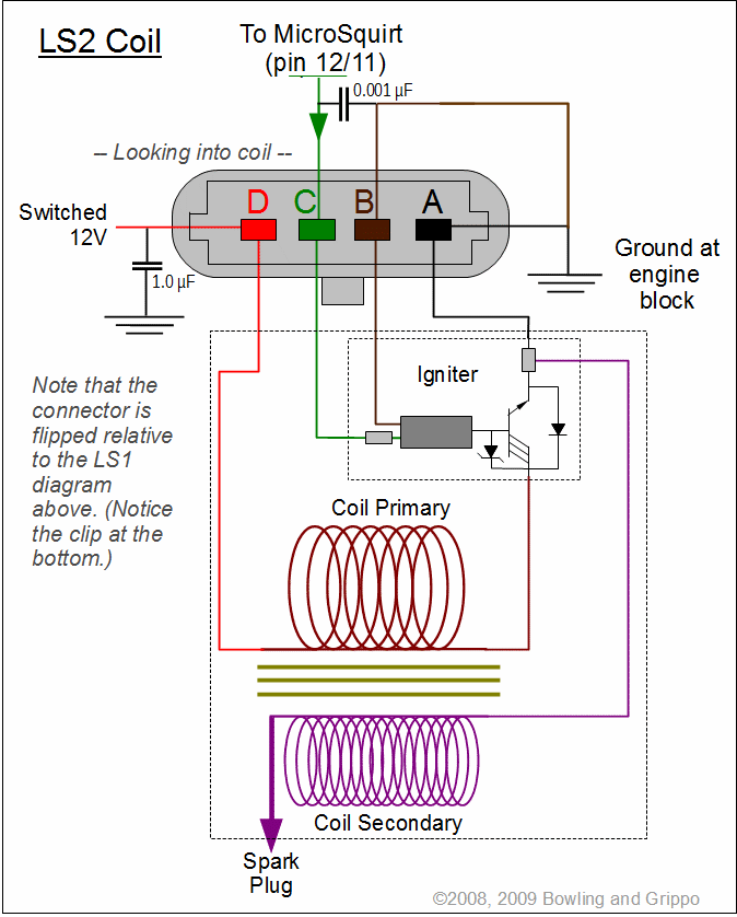
Have you ever stared at a 5.3 LS coil pack wiring diagram and felt like you were looking at a foreign language? You’re not alone. These diagrams can seem intimidating at first glance, with their dense network of wires and cryptic symbols. But fear not, intrepid mechanic or curious enthusiast: understanding the 5.3 LS coil pack wiring diagram is like unlocking a secret code to unleashing the full potential of your engine. This guide will demystify the diagram, revealing its secrets and empowering you to tackle any ignition system challenge with confidence.

Image: forums.turbobricks.com
The 5.3 LS engine, a powerhouse of American engineering, relies on a precise ignition system to ignite the air-fuel mixture in each cylinder. The coil packs, those small cylindrical components nestled near the spark plugs, are the crucial link between electrical energy and combustion. By understanding the intricate wiring that connects the coil packs to the engine control module (ECM), you gain control over the spark timing, ensuring smooth operation and optimal performance.
Navigating the 5.3 LS Coil Pack Wiring Diagram: A Visual Journey
Let’s dive into the details. A typical 5.3 LS coil pack wiring diagram consists of several essential elements, each representing a unique function within the ignition system. Here’s a breakdown of these key components:
1. Engine Control Module (ECM): The Brains of the Operation
Imagine the ECM as the engine’s command center, receiving data from various sensors and issuing instructions to other components. It determines the precise spark timing for each cylinder based on factors like engine speed, load, and throttle position. The wiring diagram will show the ECM’s connection to the coil packs, providing a clear picture of how the ECM controls ignition events.
2. Coil Packs: Delivering the Spark
Coil packs are transformers that step up low-voltage electricity from the ECM to high-voltage electricity, generating the spark that ignites the air-fuel mixture. The diagram will depict the individual coil packs and their corresponding cylinders, helping you trace the flow of electrical energy from the ECM to each spark plug.

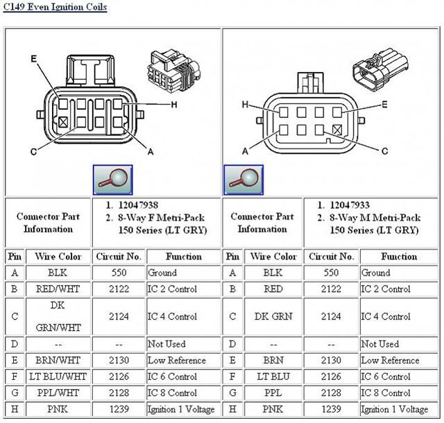
Image: s4.photobucket.com
3. Spark Plugs: Creating the Flame
Spark plugs are the final destination for the high-voltage electrical current, delivering the spark that sets fire to the fuel-air mixture. The diagram will show how each coil pack connects to a specific spark plug, ensuring the correct ignition sequence and proper cylinder firing order.
4. Wires: The Electrical Highway
Wires act as the electrical highway, carrying the high-voltage current from the coil packs to the spark plugs. The diagram will illustrate the path of these wires, revealing their connections to the coil packs, spark plugs, and other components within the ignition system.
5. Connectors: Junction Points
Connectors act as junction points, allowing the electrical current to flow between different components. In the wiring diagram, connectors are often represented by symbols or labels, indicating their locations and the wires that connect to them.
Decoding the Colors and Symbols: Language of the Wiring Diagram
Once you’ve identified the key components, it’s time to understand the language of the diagram. Wire colors and symbols speak volumes about the electrical path and the function of each connection.
1. Wire Colors: A Visual Code
Wire colors are often used to differentiate between various electrical circuits. For example, a red wire may indicate a power supply line, while a black wire might represent a ground connection. Understanding the color coding system is essential for tracing the flow of electricity and identifying potential problems.
2. Symbols: A Shorthand Language
Symbols provide a concise way to represent various components and connections within the diagram. A simple circle might represent a connector, while different shapes can depict coil packs, spark plugs, and other components. Learning the meaning of these symbols is crucial for interpreting the diagram effectively.
Tracing the Spark Path: Understanding the Ignition Sequence
With the diagram deciphered, we can trace the spark path to understand how the ignition system works. The ECM sends a signal to a specific coil pack, which transforms the low-voltage current into high-voltage electricity, ultimately triggering a spark at the corresponding spark plug. The timing of these signals is precisely controlled by the ECM, ensuring the optimal firing order for each cylinder.
The diagram becomes your roadmap for understanding how each cylinder fires in succession, resulting in the smooth and powerful operation of the 5.3 LS engine. This sequence is crucial for maintaining proper combustion and maximizing engine performance.
Troubleshooting Ignition Issues: Utilizing the Diagram for Solutions
The 5.3 LS coil pack wiring diagram is not just a theoretical exercise. It’s a valuable tool for diagnosing and troubleshooting ignition problems. When a cylinder misfires or the engine starts to sputter, the wiring diagram helps you pinpoint the source of the issue. By tracing the electrical path from the ECM to the coil pack and spark plug, you can identify any broken wires, faulty connectors, or other problems that might be causing ignition difficulties.
By understanding how the connections are supposed to be made, you can quickly identify any inconsistencies, broken wires, or loose connections. The diagram becomes your guide to restoring the flow of electrical energy, restoring the engine to its peak performance.
Beyond the Diagram: Exploring the World of LS Swaps and Tuning
The 5.3 LS engine’s popularity extends beyond its original application. It’s a popular choice for engine swaps, thanks to its performance, reliability, and availability of aftermarket parts. Understanding the coil pack wiring diagram becomes even more crucial when undertaking an LS swap. You need to ensure that the coil packs are properly wired to the ECM and the spark plugs in the new vehicle, maintaining the correct firing order and ensuring proper operation. This often involves modifying the wiring harness or using a standalone ECM that’s compatible with the new engine configuration.
Furthermore, the 5.3 LS engine is known for its tuning potential. By adjusting the spark timing, ignition advance, and other parameters, you can unleash additional performance and efficiency. The wiring diagram plays a vital role in understanding how different components interact with the ECM, helping you fine-tune the ignition system for maximum power and fuel economy.
5.3 Ls Coil Pack Wiring Diagram
Conclusion: Embracing the Power of Knowledge
The 5.3 LS coil pack wiring diagram, once a source of confusion and frustration, can transform into your secret weapon for understanding and mastering the engine’s ignition system. By decoding its secrets, you gain the confidence to diagnose and troubleshoot problems, perform engine swaps, and even unlock the full potential through performance tuning. Embrace the power of knowledge, and unlock the full potential of your 5.3 LS engine!


