
Imagine your car sputtering, struggling to accelerate, and emitting a strange cough. You’ve got a nagging feeling something is amiss, but the diagnostic light remains stubbornly silent. This, dear reader, is where the humble MAF sensor, the ‘Mass Air Flow’ sensor, steps in, playing a crucial role in your car’s oxygen-fueled dance. And when it comes to 5 wire MAF sensors, understanding their wiring diagram can be the key to unraveling the mystery behind these performance quirks.

Image: www.2carpros.com
Let’s embark on a journey to demystify the 5 wire MAF sensor, exploring its innards and unlocking the secrets of its wiring. This guide is your companion, armed with clear explanations and practical tips, to help you navigate the world of engine diagnostics and gain the confidence to tackle those perplexing car troubles head-on.
What is a MAF Sensor and Why Does it Matter?
At the heart of your engine’s efficient operation lies the delicate dance of air and fuel. To achieve this perfect balance, your vehicle relies on the MAF sensor, a tiny but mighty device nestled in your intake manifold. Think of it as the engine’s ‘air traffic controller’, precisely measuring the amount of air rushing into the cylinders. This data is then transmitted to the ECU (Engine Control Unit) which, in turn, determines the precise amount of fuel needed to create the perfect combustion.
But why does a 5 wire MAF sensor stand apart? Well, in the world of MAF sensors, the number of wires signifies the complexity of their operation. A 5 wire MAF sensor often indicates a more sophisticated design, equipped with additional features for enhanced performance and accuracy.
Dissecting the 5 Wire MAF Sensor Wiring Diagram: A Step-by-Step Guide
To understand the 5 wire MAF sensor wiring diagram, we need to delve into its core components:
1. The Hot Wire: At the heart of the MAF sensor lies the hot wire, a filament heated to a specific temperature. This filament serves as the air flow detector. As air passes over the wire, it cools down, and the sensor measures this temperature change. This measurement, combined with other variables, allows the MAF sensor to calculate the air mass flowing into the engine.
2. The Ground Wire: The ground wire acts as the reference point, providing a stable electrical path for the sensor’s operation. It ensures accurate voltage measurements by ensuring a consistent electrical potential.
3. The Signal Wire: This is the data highway, transporting the air flow measurements from the sensor to the ECU. It carries voltage fluctuations, acting as a language the ECU understands, translating the air flow readings into actionable commands.
4. The Power Wire: The power wire is the lifeline of the sensor, supplying the necessary energy for its operation. It ensures consistent power delivery, keeping the hot wire heated and the sensor functioning properly.
5. The Heater Wire: Found in more advanced 5 wire MAF sensors, this wire plays a crucial role in maintaining the hot wire’s temperature. It acts as a temperature regulator, ensuring a consistent hot wire temperature, even in varied environmental conditions. This precise temperature control is paramount for accurate air flow measurement, especially in extreme temperatures.
Interpreting the Wiring Diagram: Beyond the Wires
Reading a wiring diagram might seem daunting, but it’s simpler than you might think. The 5 wire MAF sensor wiring diagram will typically show you:
-
Color-coded wires: Each wire is assigned a specific color for easy identification. These colors act as visual cues, helping you match the wires on the sensor to the corresponding connections on the wiring harness.
-
Connections: The diagram will show how these wires connect to other components in the engine system, typically to the ECU or a specific connector.
-
Voltage and Current Information: Some wiring diagrams may also provide information about the voltage and current requirements of each wire, offering valuable insights into the sensor’s operational parameters.
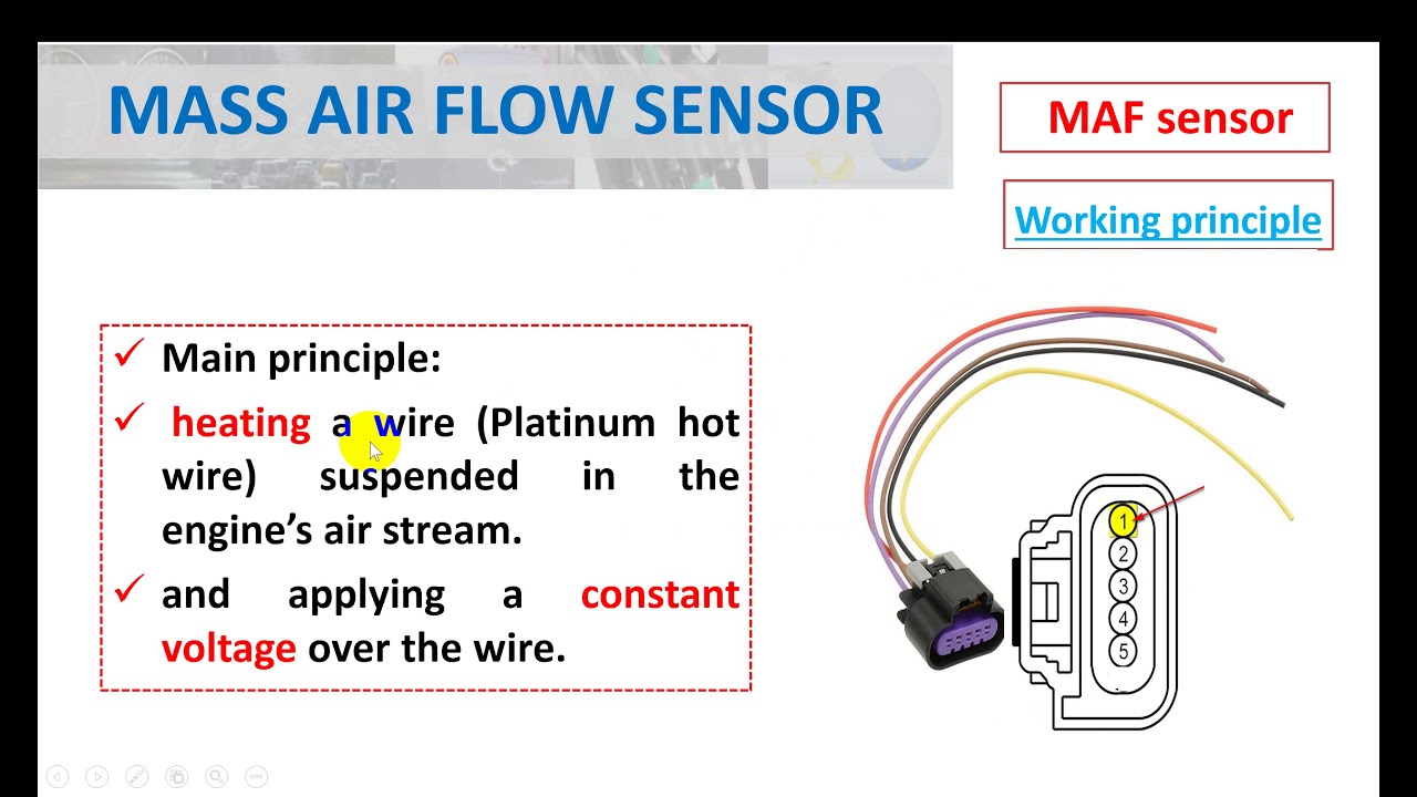
Image: diagramfixschwartz.z13.web.core.windows.net
Troubleshooting and Common Issues
Now that we’ve decoded the wiring, let’s tackle some common MAF sensor hiccups. You might encounter issues like:
-
A dirty sensor: Oil and dirt can accumulate on the hot wire, affecting its ability to measure airflow accurately. This can lead to erratic engine performance, stalling, or even a check engine light.
-
Loose or corroded connections: Oxidation or corrosion at the wiring terminals can disrupt the flow of electrical signals, leading to faulty readings.
-
Faulty wiring: Damaged or frayed wires can cause breaks in the electrical circuit, rendering the sensor dysfunctional.
Expert Insights and Actionable Tips
So, what can you do? Here’s a checklist to keep your 5 wire MAF sensor in tip-top shape:
-
Regular cleaning: A simple cleaning with MAF sensor cleaner can remove accumulated debris and restore the sensor’s functionality. Take care to avoid touching the hot wire directly to prevent damage.
-
Inspect connections: Carefully examine the wiring connections for signs of corrosion or loose connections. If needed, clean or tighten the terminals to ensure proper contact.
-
Consult a professional: If you suspect a wiring issue or a faulty sensor, seek the guidance of a trusted mechanic. Attempting to repair or replace the sensor without proper training could lead to further damage.
5 Wire Maf Sensor Wiring Diagram
The Final Word: Your Engine’s Air Traffic Controller
The 5 wire MAF sensor is a critical component in your car’s engine, acting as the air traffic controller that ensures smooth and efficient combustion. By understanding the wiring diagram, its inner workings, and potential issues, you gain the knowledge to diagnose and address problems effectively. Armed with this knowledge, you can tackle your next engine-related challenge with confidence and keep your car running like a well-oiled machine.
Keep in mind, this guide provides general information about 5 wire MAF sensor wiring diagrams. For specific details and assistance with your vehicle, always consult your car’s owner’s manual or a knowledgeable mechanic. The world of automotive diagnostics is vast, but with a little exploration and understanding, you can become a more empowered and informed driver.


